
Producing solid models for DAGMC using Cubit
The general workflow for the production of models for analysis using DAGMC looks like that shown in the Figure below.
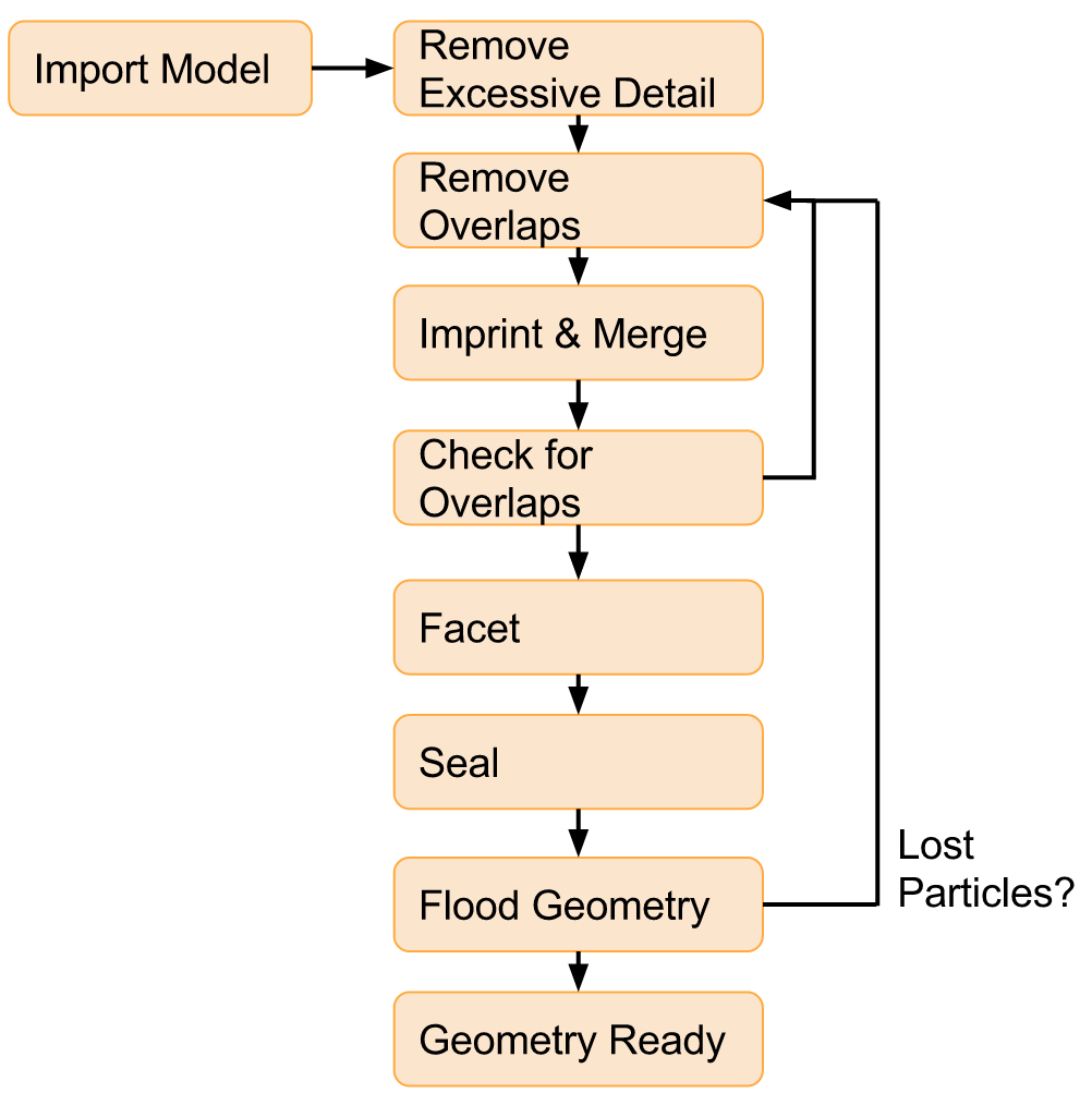
The general workflow for the production of DAGMC models is the following:
Ensure that units/sizes for DAGMC models are “cm”
Remove excessive detail (typically threads on bolts, combine washer stacks, etc.)
Inspect and resolve overlapping volumes, you may need to scale the model up to detect these
CUBIT> validate vol all
CUBIT> autoheal problem vols
Other tools:
Regularize may be needed (simplifies by removing splines, but will reverse imprint operation)
- Check and possibly remove negligibly small curves, surfaces, and volumes. (check “hydraulic” length and “regular” length)
CUBIT> group "smallsurfaces" add surface with area < 1.e-3
CUBIT> group "smallcurves" add curve with length < 1.e-4
CUBIT> group "smallvols" add volume with volume < 1.e-5
Create pre-imprint/merge table of volume of volumes, and then imprint
CUBIT> imprint body all
Merge model, in Cubit
CUBIT> merge all
You may also wish to add a merge tolerance (this must be done before merging)
CUBIT> merge tol 1e-6
Validate model, in Cubit
CUBIT> validate vol all
re-check for overlapping volumes and now also check for overlapping surfaces
create post imprint/merge table of volume of volumes (use volofvolcubit.py)
compare pre and post-imprint/merge model volume of volumes
inspect volumes in pre-imprint model with significant change in volume
re-check for small areas, curves, volumes
any problems in these steps repair volumes in pre-imprint model and go back to step 3
Facet model
CUBIT> export dagmc "geom.h5m" faceting_tolerance 1.0e-4
Seal model if possible (use make_watertight)
Flood and/or transport particles in model
If lost particles or leaky:
examine lost locations (use mklostvis.pl)
examine “leaks”/tunneling (can use a mesh tally to locate)
repair the pre-imprint/merge model (go to step 2)
If no lost particles or leaks, then the model is ready for transport
Preparing solid models
In theory, solid models can be prepared in any modeling software system (e.g. SolidWorks, Pro/E, Catia, etc). What is most important about the choice of solid modeling system is the ability to export to a format that can be imported by Cubit, in particular:
ACIS (*.sat)
STEP (*.stp, *.step, etc)
The ACIS format is strongly recommended due to its ability to retain imprint and merge information, and there is anecdotal evidence that ACIS files lead to a more successful model pipeline. Ansys Spaceclaim is often used at UW - Madison to perform model cleaning and defeaturing, which can import many of the common CAD formats and exports to ACIS.
There are a number of concepts to consider while preparing a solid model; however, the most important considerations are small gaps and overlaps that might exist in the model. These gaps and overlaps can lead to rapid failure when running a DAGMC-based analysis. The following steps are provided to help make a more robust model before running your DAGMC-based analysis.
Beware: obtaining a robust model may be an iterative and time consuming process. In some cases, the validity of the model will require running a DAGMC-based analysis and assessing whether or not the model yielded expected results or a small enough number of lost particles. If the results did not meet expectations, changes to the model may be in order.
Knowing the model
The first consideration to address is where the solid model originated and for what purpose. In many instances, models constructed for manufacturing purposes will have tolerances that are undesirable for particle transport applications. For example, a gap might exist between fuel pellets and the cladding wall for a PWR fuel rod. While this is perfectly acceptable for an individual manufacturing the rod, the gap could potentially present problems in a DAGMC-based analysis, depending on how it is modeled.
Knowing who created the model and to what purpose provides a starting point for preparing the model. If it was made with particle transport in mind, then very little work may be needed; but as with the example above, some models may require changes to accommodate the needs of a DAGMC-based analysis.
Identifying weaknesses in the model
When assessing a model that is to be used for particle transport two primary concerns must addressed. These concerns are:
Gaps
Overlaps
Gaps occur when the surfaces of two volumes/parts that should be in contact are set apart from each instead of having coincident surfaces. The size of the gap is generally unimportant, for most solid modeling programs, a gap is a gap. The desired result is to have all surfaces of volumes/parts to be coincident. If coincidence is not achieved, particles may become lost when entering the region between the surfaces.
Overlaps are found where two or more volumes/parts encroach upon the same space. As with gaps, the magnitude of the overlapping volume is usually unimportant. When a particle enters a region of overlap, it may not correctly determine which volume/part it resides in. If this occurs, the particle may become lost.
Identifying gaps and overlaps may be difficult and time consuming; however, some 3D modeling programs like SolidWorks have built in tools to identify these occurrences. Rely on the modeling program to identify these problematic features and use the steps in the next section to change, reduce and remove their effect on the model.
Modifying your model
Once the gaps and overlaps in the model have been identified, the three following methods may be used to change, reduce, and remove their effect on the model.
Create “voided” geometries
Modify volume/part dimensions
Remove superfluous details
Each method is discussed in detail below:
As with the fuel rod example mentioned above, some regions that are ‘gaps’ are also important. Instead of removing the gap entirely (by changing the dimensions of the cladding or the fuel to force coincidence), a new volume/part could be modeled that coincided with the outer diameter of the fuel AND the inner diameter of the cladding. Now a “voided” geometry occupies the previously unaccounted for region. By specifying these “voided” geometries in a DAGMC-based analysis, the physical importance of the region can be retained while accomodating the requirement of having coincident surfaces.
Another method to resolve gaps and overlaps is to simply change the dimensions of the volume/part (eg: making a dimension several cm bigger or smaller to ensure coincidence surfaces). In many instances this method could compromise the physics of the solution and is then undesirable. However, in other instances, this solution is very logical. One particularly significant example is if different volumes were modeled with different unit systems. For example, one volume/part might have been model in [in] while its neighbor was modeled in [cm]. While surfaces may be nearly coincident, rounding errors might prevent coincidence from occurring. A simple change to one dimension may hardly change the volume/part’s characteristics yet result in coincidence.
Finally, superfluous details may prevent a volume/part from coinciding with its neighbors properly. A potential solution is to simply remove the superfluous detail to simplfy the model and ensure the desired surfaces are coincident. Some volumes/parts will inherently hurt the model’s effectiveness either due to its complex features or small dimensions. A volume/part’s effect on the model cannot truly be assessed until a DAGMC-based analysis is run. This final method is usually implemented in an attempt to reduce the number of lost particles while maintaining the most important characteristics of the system.
Note: Of all steps, the removal of superfluous details is the most subjective and heavily dependent on the model’s intended application.
Assessing your model
Lost particles are undesirable; lost particles usually indicate weaknesses and failures within the geometry. While the goal of the DAGMC project is to guarantee that there will never be lost particles, they can occur even on robust geometries. It is up to the user/analyst to determine what lost particle rate they consider acceptable. The UW-Madison group usually considers lost particle rates that are less than 1/5,000,000 to be a threshold for most problems. It is important to understand whether particles are being lost from an important region of your phase space.
The implicit compliment is automatically generated by DAGMC upon loading a geometry; it is composed of all the space that is not defined by the CAD geometry. It is often convenient to not define all space in a given model, for example the space inside a tokamak which is occupied by air or vacuum, or the water volume in a reactor. The power of the implicit compliment lies in the fact that it is not a true CAD body since it was never defined, but it automatically defines all undefined space in the model.
Finishing up and final notes
Having prepared your model to completion with the appropriate groups created , you can choose to save your model in various formats. Previously we recommended ACIS *.sat files, but any format that reliably retains imprortant metadata will suffice. Recommended storage formats are ACIS or *.cub files.
One should also use the make_watertight. tool on the produced DAGMC *.h5m file in order to completely seal your geometry, this should help prevent tolerance issues due to faceting.