
Cubit basics
Pre-processing solid models using Cubit
This section focuses on steps that are independent of the Monte Carlo code used for analysis. Additional steps for the unified workflow, UW2, or Monte Carlo code-specific workflows may be followed as needed.
Importing the solid model
The first step in Cubit is to import the generated solid model. Depending on the complexity of the model, this step can take several seconds up to a half an hour. As an initial user, it is recommend to start with simple models and geometries to obtain a better understanding of Cubit.
Imprint and merge
For a DAGMC based analysis to work optimally, all of the surfaces must be imprinted and merged. Imprinting creates a common surface interface between touching volumes. Merging then takes the touching surfaces and makes them into one surface. The imprint operation is shown below.
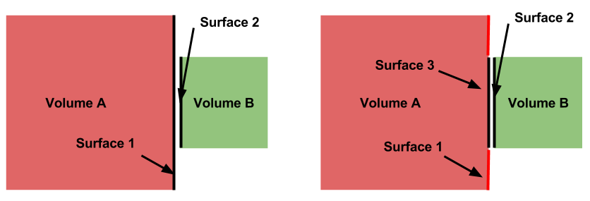
To imprint, issue the following command:
CUBIT> imprint body all
Should the imprint be successful, then the next step is to merge the geometry. A schematic of what the merge operation achieves is shown below.
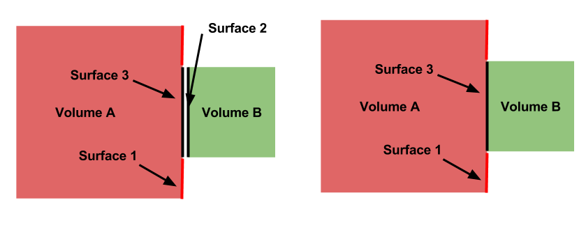
Sometimes it may be important to specify a merge tolerance. To set the tolerance and merge, issue the following commands:
CUBIT> merge tol 5e-7
CUBIT> merge all
This process can be very time consuming. For large models of several thousand volumes, the imprint and merge steps can take several hours. However, for small geometries (on the order of 100 volumes) the process is rather quick.
Grouping volumes and surfaces
A DAGMC-based analysis allows a number of attributes of the geometry to be defined within the geometry file. These characteristics generally relate to the physical behavior of the volume, for example its material definition or boundary conditions.
Before the discussion of specific attributes, the practice of “grouping” needs to be explained. A group is essentially a collection of volumes or surfaces that share a common attribute; the practical usage of “grouping” will be explained in the next section.
The general format for creating/adding volumes to a group is:
CUBIT> group "group.name" add vol/surf ...
For example, to create a group called “moderator” containing volumes 5, 6, 7, and 10, the following command would be used:
CUBIT> group "moderator" add vol 5 to 8 10
Another example, shows that groups don’t have to just contain volumes, but can contain surfaces too. Below the group “shield.boundary” is created with surfaces 16 and 37:
CUBIT> group "shield.boundary" add surf 16 37
Due to the importance of using the group command reading the
CUBIT manual
section on its full usage is highly recommended.
Production of the DAGMC geometry
Now that the geometry is ready for DAGMC we must export it. Using the Cubit plugin make this very straightforward, assuming that the user has proceeded through the previous steps then all one must do is use the export dagmc command.
CUBIT> export dagmc <filename> [faceting_tolerance <faceting tolerance>]
                               [length_tolerance <length tolerance>]
                               [normal_tolerance <normal tolerance>]
                               [verbose] [fatal_on_curves]
The meaning of these different options are described below
- Faceting Tolerance - Specifies how far a facet is allowed
to be from the CAD representation of a surface in the faceting algorithm.
- Lenth Tolerance - Specifies the maximum allowed length
of a facet edge.
- Normal Tolerance - Specifies the maximum allowed change
in angle between then normal vector of two adjacent facets.
For example to produce a file called, geometry.h5m with faceting tolerances and length tolerances of 1.0e-4 cm and 5.0 cm respectively
CUBIT> export dagmc geometry.h5m faceting_tolerance 1.e-4 length_tolerance 5.0
The time taken to perform this step depends upon the complexity of the model, it could take seconds for very simple models to hours for very complex models. It is also possible that faceting artifacts or failures could occur at this point, so monitor the output of this command in the Cubit command line. If issues due occurs, these should be addressed following the workflow listed above.
Where faceting_tolerance, normal_tolerance, and length tolerance are optional arguments. For example, to export the currently loaded file to a file called “large_facets.h5m” with a faceting tolerance of 1.e-5, use
CUBIT> export dagmc "large_facets.h5m" faceting_tolerance 1.e-5
Roadmap for the future
Currently we have a number of standalone command line tools that are run sequentially on a model following faceting using Cubit. We run make_watertight to seal models to ensure no topological weaknesses exist and we run uwuw_preproc to add materials into analysis geometries. It is envisioned that at some point in the near future that we will integrate these as options within the Cubit plugin.
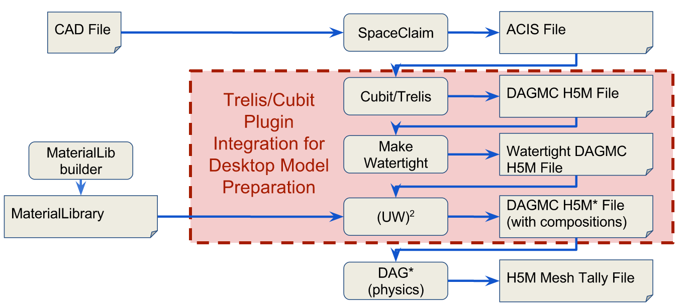
This will allow you to add additional options if you want the model to be made watertight and/or if you want to add materials to the resultant geometry. There will always be power users that prefer the command line tools. These tools will continue to be supported with identical infrastructure.