
Developer’s theory guide
This guide is meant to give developers a comprehensive understanding of how DAGMC works as it exists in MOAB and the key components one may use during development.
Constructor
To initialize a DAGMC instance, the constructor must be called. If the constructor is called with no arguments, then a new MOAB instance is created and attached to the DAGMC instance. Otherwise, a pointer to an existing MOAB instance can be passed in the constructor and a DAGMC instance will be attached to that existing MOAB instance.
DAGMC setup
There are three main steps to setting up a DAGMC geometry. First the storage space for the implicit complement is created. Then the OBB trees are built. And finally the sets of indices for volumes and surfaces are generated. See sections below for more information about implicit complements, OBBs, and indices.
Topology
Every mesh-based geometry contains entity sets that are either volumes, surfaces, or curves. There are two types of relationships that can relate entities to other entities. The first is called a parent-child relationship. Volumes are parents to surfaces that make up that volume; surfaces are parents to curves; and curves are parents to the geometric vertices.
The second type of relationship is the set relationship, which is different from a parent-child relationship. Each surface and curve is an entity set. The surface entity sets contain the triangles and their vertices for that surface. The curve entity sets contain edges and their vertices. The volume entity sets, however, are empty. While a volume is parent to surfaces (the parent-child relationship), the volume does not contain any mesh entities.
Indices
Types of indices
There are three ways to identify any surface and volume in a geometry: global ID, index, or entity handle. The global ID is an integer number that corresponds to the Cubit ID. As a result, the set of global IDs does not necessarily have to be contiguous. During setup, the global ID is tagged on the entity set. The second method is to identify by index. This is an ordinal numerical reference for each volume or surface in the geometry. It is important to note that index starts from one (not zero). The third method is to identify by the entity handle of the entity set. The entity handle is assigned by MOAB and is not necessarily contiguous.
Cross referencing
If one type of index is known, then either of the other two can be determined.
By using the functions below or a combination of the functions, either global ID,
index, or entity handle can be determined. It is important to note that surfaces
and volumes each have their own set of integer indexes and global IDs, while
entity handles are unique to each entity set. Each integer (whether it is an
index or global ID) can refer to multiple entity handles (a surface or volume).
Therefore, when cross referencing by either index or global ID, the dimension
needs to be supplied, but is not necessary when cross referencing by entity
handle. There are five methods for cross referencing: entity handle by index
(entity_by_index), global ID by index (id_by_index), entity handle by global
ID (entity_by_id), global ID by entity handle (get_entity_id), index by entity
handle (index_by_handle).
OBB Tree
What is an OBB?
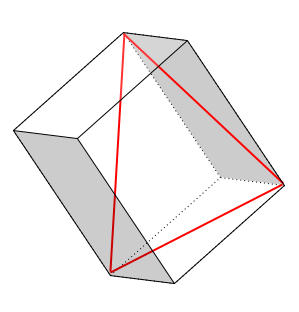
An OBB, or Oriented Bounding Box, is a box that contains a single facet or set of facets and is oriented such that it is the smallest possible box encompassing the facet(s), as opposed to having an axis aligned with the full geometry. This is different from an axis aligned bounding box, which is aligned with the global axis and is not necessarily the smallest box possible. An example is the facet outlined in red below and it’s corresponding OBB. For the the rest of this section, facets will be represented by a line with a 2D OBB.
OBB tree construction
First, the OBB tree for each surface is built. This is built top down where the top level is an OBB that contains all the surface’s facets. Then the set of facets is split roughly in half and two new OBBs form around each of the new sets. This continues until each of the OBBs the level contains a small number of facets. A 2D example is given below where a single surface has been faceted and the corresponding OBB tree is created.

After OBB trees have been created for each surface in a geometry, they are joined together to create a complete OBB tree for a volume. See the example below where the green, red, and blue surfaces make up a volume.

Implicit complement
What is the implicit complement & how is it formed?
The implicit complement is the space not defined by the CAD model. It is formed by looking at the sense(s) of each surface individually. A surface between two volumes has both a forward and reverse sense defined with respect to the volumes. A surface that has only one sense defined, whether it is forward or reverse, means that only one side of that surface has a volume defined. The collection of all surfaces in the geometry that only have one sense defined are the surfaces that create the implicit complement by changing the sense already defined.
OBB tree construction
The OBB tree construction for the implicit complement is very similar to the construction of OBB trees for general volumes. However, since the surfaces that make the implicit complement are all part of other volumes, the OBB trees for the surfaces are already known, and therefore the only construction step necessary is joining the trees to create a complete OBB tree for the implicit complement volume.
Ray history
DAGMC implements a class called RayHistory which is local to the DAGMC class.
The ray history stores a vector containing all the entity handles of the triangles
that the ray has crossed. This structure can be emptied (reset), the last
entry can be popped off and removed (rollback_last_intersection), or the
entire history can be removed with the exception of the last intersection which forms
the basis of the new RayHistory (reset_to_last_intersection). The purpose of the
class is to improve robustness of the ray queries inside of DAGMC for a number of
purposes:
When a particle is streaming, to ensure that the same triangle cannot be hit twice
When a particle is reflecting from a surface, to clear all history except the triangle just hit
When a particle is newly created or retrieved from the bank/stack and the RayHistory should be cleared
When a particle step was not fully taken, for example a sensing step or an interaction occurred first, the RayHistory should be taken back to its previous state such that the triangle could be hit again.
The RayHistory class is an optional argument to the DAGMC ray functions, which will otherwise not retain nor exclude any intersections other than those not numerically possible.
Point in volume
Given a volume entity handle, position, and ray direction (optional), the
point_in_volume function will test if the point is inside or outside the given
volume. It is assumed that the test volume exists and is known. Passing a
direction vector to this function adds robustness and ensures consistent results.
Otherwise, a random direction is used.
Ray fire
The ray_fire function will return the entity handle of the next surface to be
crossed along with the distance to that surface given the ray’s direction. If
the ray is being tracked in a straight line through multiple volumes, passing
in the ray-history is important to keep the ray from intersecting facets more
than once (ie, if the particle is streaming). It is important to note that
when tracking through multiple volumes, ray_fire must be called multiple times
as it may only be called for a single volume at a time.
Next volume
If the next surface is known (after calling ray_fire), the entity handle of the
next volume can be determined by calling next_volume. Given the next surface and
the known current volume, the next volume is determined by looking at the other
volume tagged on that surface (as described in the Sense Tags section above).
This assumes that a valid surface and volume are provided. If no next volume
exists, then the call will return 0 for the next volume.
DAGMC Metadata
Metadata Structure in DAGMC Files
This section describes the structure used to represent DAGMC metadata using MOAB’s .h5m format. This is useful knowledge when constructing DAGMC geometries manually or when adding support for their generation from a new source.
Metadata EntitySets are tagged with a CATEGORY tag (similar to geometric sets) with the value “Group” to indicate that the entity set’s purpose is to group geometric entities together. These metadata EntitySets can be gathered using this tag and value to identify “Group” entity sets in the MOAB instance.
DAGMC metadata information used during simulation (material assignments, boundary conditions, volume tallies, etc.) is stored on these “Group” EntitySets as the value of their NAME tag. Please see the UWUW Section of the user’s guide for information about the syntax of this tagged information. Geometric EntitySets associated with this metadata entry are contained by the metadata entity set.
- 1
only used in DAG-MCNP simulations.
DAGMC’s Metadata Interface
DAGMC’s metadata interface allows one to navigate metadata in more
straightforward ways than querying MOAB tags directly, allowing one to retrieve
entities with specific attributes quickly. The metadata class is constructed
using an existing DAGMC class. Upon calling load_property_data, the
interface will parse all metadata existing in the MOAB file with keywords, such
as “mat” or “boundary”, which are provided to the interface in its
constructor. A list of the default keywords is provided below. Additional
keywords can be provided to the interface during its construction to support
implementation-specific conventions.
- Default metadata keyword list:
mat: material composition assignment
rho: material density assignment (units: g/cc)
boundary: boundary condition
tally: indicates a geometric tally on a surface or volume
importance: used to set variance reduction properties 1
The mat and rho keywords are required for all DAGMC simulations for full
material definitions in each volume of the model.
Once the metadata in the MOAB file has been parsed, the interface contains
functions like get_surface_property and get_volume_property which allow
one to retrieve metadata values for a keyword using the surface/volume index or
MOAB entity handle.
The University of Wisconsin Unified Workflow (UWUW) Interface
The UWUW class in DagMC uses an amalgamated version of PyNE’s C++ code to interface with PyNE material and tally libraries. PyNE’s “physics code neutral” data formats allow the data in UWUW DAGMC files to interface with many different physics codes using the same .h5m file.
Standard Use
The UWUW class is typically constructed using the path to a .h5m file containing a material library. Both material and tally definitions along with their assignment to EntitySets in the MOAB geometry are loaded into the UWUW instance upon its creation.
UWUW* uwuw = new UWUW("/path/to/dagmc.h5m");
UWUW will search the hdf5 file to find material and tally definitions in the
default datapaths /materials and /tally, respectively. At this point,
material/tally library information can be accessed via the material_library
and tally_library attributes of the UWUW object.
int mat_lib_size = uwuw->material_library.size();
pyne::Material steel = uwuw->material_library["Steel"];
Material and tally information can then be written in a variety of supported formats using their writer methods, named for each of the physics codes they support.
std::string mcnp_mat = mat.mcnp();
For more information on supported codes and how to gather other information from these objects, please refer to the PyNE’s material and tally documentation.
The UWUW class relies on the DAGMC’s Metadata Interface to parse material and
tally assignments from the MOAB geometry in the DAGMC .h5m file using its
default set of keywords. In particular, the mapping of material definitions to
geometric EntitySets generated by the DAGMC metadata class is directly
transferred to the UWUW class in the process_materials method. Certain
utility functions of DAGMC’s metadata class like unpack_string are used in
UWUW as well for convenience in other areas of UWUW as well.
Custom hdf5 datapaths
While it is recommended that the default hdf5 datapaths for PyNE data are
used. It is possible to provide specific datapaths to the interface. This can be
done by creating a UWUW object with an empty constructor. This will subvert the
automatic loading of material and tally data that would occur using the
constructor shown in the previous section. The load_pyne_materials and
load_pyne_tallies methods can then be used to provide custom material/tally
library files and/or customized hdf5 datapaths for those files. 2
UWUW* uwuw = new UWUW();
uwuw->load_pyne_materials("hdf5_material_file_path", datapath = "/custom/hdf5/datapath");
uwuw->load_pyne_tallies("hdf5_tally_file_path", datapath = "/custom/hdf5/datapath");
- 2
Note: It is important to specify absolute filepaths if using a UWUW object in this way. UWUW contains a
get_full_filepathmethod for convenience.